Head tracking with BlazeFace
BlazeFace identifies faces. This is great, but I want to identify something slightly different: heads. Here I show my method for calculating a bounding circle around a head, given only the facial landmarks. You can run it on your own face: to start a demo!
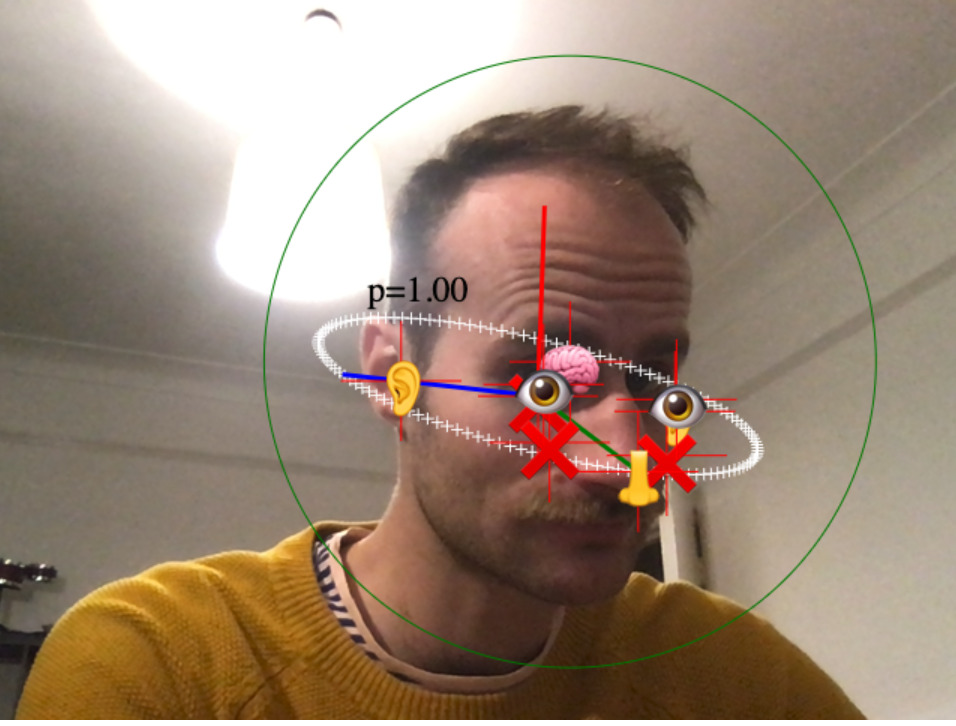
And here’s what I get when I run it against my own face:
In a previous post, I showed the “hello world” of BlazeFace. It runs BlazeFace on your webcam video stream, takes the face landmarks and bounding box output by BlazeFace, and displays them on a canvas.
BlazeFace returns a bounding box, but it’s not clear what it is supposed to be bounding. For example, the box ignores the hair, chin, and cranium. It bounds the facial landmarks, though not precisely. Instead, I want a circle that bounds the head in the image. This circle will be the image of a sphere that tightly bounds the head in three dimensions.
Here’s how I calculate that circle. We ignore the bounding box that BlazeFace gives us, and instead calculate our own bounding circle from the landmarks that BlazeFace gives us, which are:
const rightEye = prediction.landmarks[0];
const leftEye = prediction.landmarks[1];
const nose = prediction.landmarks[2];
const mouth = prediction.landmarks[3];
const rightEar = prediction.landmarks[4];
const leftEar = prediction.landmarks[5];
Here’s an image illustrating the BlazeFace landmarks in magenta on a model head. BlazeFace doesn’t define exactly what it means by “nose”, “ear”, et cetera. And it’s inconsistent; e.g. when viewing my head from below, the identified “ear” points are quite far from my ears. Below, I’ve just marked the points that BlazeFace seems to identify most strongly.
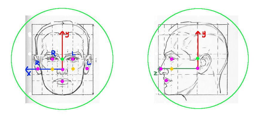
I’ve labelled “L” for “left” and “R” for “right” on this image. Note that BlazeFace’s notion of “left” is on the right side of the image; it’s what you mean when you say “my left ear”.
I’ve fixed a coordinate system on this image. The origin of the coordinate system is the midpoint between the ears. The image shows x, y and z unit vectors. We can then define the 3D position of the facial landmarks that we will use:
const MODEL_HEAD_EAR_COORD_X = 0.7;
const MODEL_HEAD_RIGHT_EYE_COORD = [ 0.3, 0.3, 0.7 ];
The center of the bounding sphere should be the center of the head. But the “center of the head” is a fuzzy concept! By experimentation (i.e., drawing circles around the heads in the drawing above), I define the center of the head as the point shown in bright green in the image above, and I define the radius of the bounding sphere with the green circle in the image above. These have these values:
const MODEL_HEAD_BOUNDING_SPHERE_CENTER_COORD = [ 0, 0.3, 0.3 ];
const MODEL_HEAD_BOUNDING_SPHERE_RADIUS = 1.35;
Note that all these figures are only for the man in the drawing! Our model will have a bias towards this artificial man! We should try to find values that work for everyone, but I don’t try that here.
In what follows, I assume that the image we get is a parallel projection of the head. That is, I assume that points in 3D space are projected onto the image with a function like this:
const origin, unitX, unitY, unitZ; // our job is to infer these!

function project(worldCoord) {
  return vec2_add(
    origin,
    vec2_mul(unitX, worldCoord[0]),
    vec2_mul(unitY, worldCoord[1]),
    vec2_mul(unitZ, worldCoord[2])
  );
}
This assumption is wrong (the camera will have some kind of perspective view), but I think the error is small.
Our job now is to infer origin, unitX, unitY and unitZ.
Conveniently,
the origin of our coordinate system is defined as the midpoint between the ears.
This can be calculated with no 3D math:
const origin = vec2_avg(leftEar, rightEar);Next,
notice that our z unit vector is, by definition,
conveniently equal to the nose point at x=0, y=0, z=1.
So we can calculate:
const unitZ = vec2_sub(nose, origin);Next we’ll calculate unitX.
Notice that rightEar is just 0.7*unitX,
because we’ve defined its position as x=0.7, y=0, z=0.
So we can calculate unitX as rightEar/0.7,
or:
const unitX = vec2_mul(vec2_sub(rightEar, origin), 1/0.7);Finally we need to infer unitY.
I believe it’s possible to infer unitY just from unitX and unitZ.
Perhaps something like the cross product.
However, my math sucks, so instead,
I use the eye positions to infer unitY.
We can calculate the projection of the model eyes on the xz-plane,
like this:
const leftEyeOnXZPlane =  vec2_add(origin, vec2_mul(unitX, -MODEL_HEAD_RIGHT_EYE_COORD[0]), eyesZ);
const rightEyeOnXZPlane = vec2_add(origin, vec2_mul(unitX,  MODEL_HEAD_RIGHT_EYE_COORD[0]), eyesZ);
Then the difference between these and the BlazeFace reported eyes tells us the direction of y:
const eyesY = vec2_avg(  // Avg because we expect the vector for each eye to be the same
  vec2_sub(leftEye, leftEyeOnXZPlane),
  vec2_sub(rightEye, rightEyeOnXZPlane)
);

const unitY = vec2_mul(eyesY, 1/MODEL_HEAD_RIGHT_EYE_COORD[1]);
Now that we have the origin and unit vectors, we can calculate the pixel position of the head center by projecting its world coordinate:
const boundingCircleCenter = project(MODEL_HEAD_BOUNDING_SPHERE_CENTER_COORD);Next, we must calculate the radius of the bounding circle.
We have defined the radius of the bounding sphere as 1.35 times the unit circle radius.
So we just need to find the radius of the unit circle in projection coordinates.
There is surely a math way to do this,
but I do it the programmer way:
draw a unit circle around the origin,
and take note of the longest line:
let unitLength = 0;
for (const p of xzUnitCirclePoints) {
  const projectedUnitCirclePoint = vec2_add(
    vec2_mul(unitX, p[0]),
    vec2_mul(unitY, p[1]),
    vec2_mul(unitZ, p[2])
  );
  unitLength = Math.max(unitLength, vecLength(projectedUnitCirclePoint));
  drawPoint(vec2_add(origin, projectedUnitCirclePoint));
}

const boundingCircleRadius = unitLength * MODEL_HEAD_BOUNDING_SPHERE_RADIUS;This page copyright James Fisher 2020. Content is not associated with my employer.
 Granola